What is the Modbus Protocol & How Does It Work?

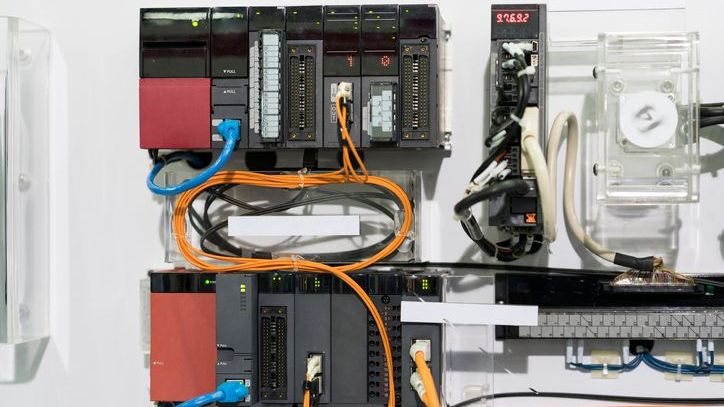
Modbus is a communication protocol that is great at connecting Modbus devices such as programmable logic controllers (PLCs) for control and data acquisition. It is the most commonly used industrial protocol and is widely accepted due to its simplicity, flexibility, and robustness.
This article does not cover every single thing about Modbus but should provide you with the knowledge to understand the Modbus protocol, the parameters and settings of Modbus, and the common ways of working with a Modbus device, especially within the field of testing.
How Does Modbus Protocol Work?
Modbus follows a client/server architecture, where the Master device initiates communication with one or more Slave devices. The Master typically sends a request to read or write data, and the Slave responds accordingly. Each Slave on a network has a unique address that differentiates it from other devices.
Modbus supports various communication methods, including Serial (RS-485) and Ethernet (TCP/IP). Each communication method has its advantages and limitations, making it suitable for different industrial applications.
There is also a Modbus ASCII method, which converts binary data into ASCII characters. But I haven't used Modbus ASCII, only the two other methods. Therefore I haven't included this method in this article.
Modbus messages consist of a header followed by data and an error-checking field. The header contains the address of the clint device, the function code that specifies the type of request, and additional information depending on the function code used.
The data field contains information such as register addresses, values to be written or read, or specific commands for control functions. The error-checking field, usually a CRC or LRC, ensures the integrity of the message during transmission.
Below is an explanation of the different terms just used.
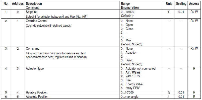
Modbus Registers and Data Types
Registers are fundamental elements in a Modbus data model, as they store data that is transmitted between the Master and client devices. These registers can hold various types of data, depending on their specific use case. Some of the most commonly used data types in the Modbus data model include:
- Coil: A coil register is a Boolean data type that can only have two possible values - True or False. It is commonly used to represent the state of digital inputs and outputs in a PLC.
- Discrete Input: A discrete input register is a Boolean data type that represents the state of a digital input. It is used for monitoring purposes and cannot be written to.
- Input Register: An input register is an integer data type that holds 16-bit values. It is often used to represent analog values or process variables in industrial systems.
- Holding Register: A holding register is an integer data type that also holds 16-bit values. It is used for both reading and writing data.
By understanding the different types of registers and their corresponding data types, developers can design efficient communication protocols that cater to specific application requirements. Additionally, with proper data mapping and translation techniques, it is possible to bridge the gap between different data types and facilitate seamless communication within a Modbus network.
Common Modbus Function codes
The Modbus protocol is a widely used communication protocol that defines a diverse range of function codes to cater to different types of data requests. These function codes play a crucial role in determining the response of the client device when a request is received from the Master.
By leveraging these function codes, the Modbus protocol enables seamless communication and efficient data exchange within a Modbus network using the protocol data unit (PDU).
Here are some of the most common function codes:
- Read Coils (Function Code 01): This function code allows the Master to read the status of digital output coils. It provides valuable insights into the state of these coils, which are often used for controlling various devices or equipment.
- Read Discrete Inputs (Function Code 02): With this function code, the Master can retrieve the status of discrete input contacts. These inputs are typically used to monitor the state of external devices or sensors, providing valuable information for decision-making processes.
- Read Holding Registers (Function Code 03): This function code enables the Master to read data from holding registers in a Programmable Logic Controller (PLC). Holding registers are used to store important data values, such as setpoints or process variables, allowing for efficient data retrieval and control.
- Read Input Registers (Function Code 04): By utilizing this function code, the Master can read data from input registers in a PLC. Input registers are commonly used to store real-time data from external devices or sensors, providing valuable information for monitoring and analysis purposes.
- Write Single Coil (Function Code 05): With this function code, the Master gains the ability to control a single digital output coil. It allows for the activation or deactivation of specific devices or equipment, providing precise control and automation capabilities.
- Write Single Register (Function Code 06): This function code enables the Master to write a value to a single holding register. It is commonly used for setting specific parameters or thresholds in a PLC, facilitating customization and adaptability.
- Write Multiple Coils (Function Code 15): This function code allows the Master to write multiple values to digital output coils. It provides the capability to control multiple devices or equipment simultaneously, enhancing efficiency and automation.
- Write Multiple Registers (Function Code 16): By utilizing this function code, the Master can write multiple values to holding registers in a PLC. It enables the setting of multiple parameters or thresholds, offering greater flexibility and customization options.
These function codes are common when connecting industrial electronic devices to a Modbus network. The Modbus manual always specifies which function codes have been implemented and the specific data address ranges for each function code. By understanding the different types of Modbus function codes and the corresponding data address, you can easily read and write the data model and the different data types.
Finally, it is essential to note that while these are some of the most commonly used function codes, there are many more available in the Modbus protocol specification to accommodate diversity.
Modbus Addresses
In a Modbus network, each clientdevice is assigned an address that uniquely identifies it within the system. These addresses are essential for establishing communication between Master and Slave devices and ensuring that data is transmitted to the correct destination. There are two types of addresses commonly used in Modbus:
- Logical Address: The logical address is a single-digit or double-digit number, ranging from 0 to 247, that identifies a Slave device in the network. It is often used for addressing individual devices and must be unique within the system.
- Physical Address: The physical address is a combination of two bytes (four digits), ranging from 1 to 65535, that specifies a specific register or coil within a Slave device. It is used to access specific data values within a device and must be unique for each register or coil.
Having well-defined addresses is crucial for efficient data exchange within a Modbus network. With logical and physical addresses, developers can easily identify and retrieve the desired data values from Slave devices, facilitating seamless communication and enabling effective control and monitoring systems.
By understanding these fundamental concepts, developers can leverage the Modbus protocol to design robust and efficient communication systems for various industrial applications.
Modbus Protocol Variants
Over the years, the Modbus protocol has evolved to cater to different types of applications and network configurations. Today, there are various variants of the Modbus protocol, each with its unique features and functionalities.
Modbus RTU
Modbus RTU (Remote Terminal Unit) is the most commonly used variant of the Modbus protocol. It utilizes a serial communication interface, such as RS-485, to establish communication between devices. The data transmission in Modbus RTU is done using binary code, making it highly efficient and less prone to errors.
Advantages of Modbus RTU:
- Simplicity, efficiency, and reliability
- Compact data size for faster and more efficient transmission
- Long-distance communication capability with serial interface
- Scalability with up to 32 devices on the same network
Disadvantages of Modbus RTU:
- Lack of built-in security features
- Potential vulnerability to unauthorized access and cyber threats
- Requires careful setup and configuration to avoid network issues
- Susceptibility to electrical noise in industrial environments impacting data integrity.
Modbus TCP/IP
Modbus TCP/IP (or Modbus ethernet) is another widely used variant that leverages Ethernet as the communication to Modbus TCP devices. It enables high-speed data transmission and allows for the creation of larger Modbus networks with multiple Masters and Slaves. Additionally, it offers greater flexibility and security features compared to Modbus RTU.
Advantages of Modbus TCP/IP:
- High-speed data transmission with Ethernet interface
- Easy integration with existing industrial networks and devices
- Built-in security features, such as encryption and authentication, for enhanced protection against cyber threats
- Scalability with the ability to connect up to 255 Slaves on a single network.
Disadvantages of Modbus TCP/IP:
- Higher installation and maintenance costs due to the use of Ethernet interface
- Requires specialized knowledge and equipment for setup and configuration
- Susceptibility to network congestion or failure impacting data exchange.
How to Connect to a Modbus Device
Connecting to a Modbus device involves several steps, including hardware configuration, addressing, and establishing communication protocols. Here's a general step-by-step guide:
- Start by identifying the type of Modbus network you are using (RTU or TCP/IP) and ensure that all devices on the network support it.
- Configure your Master device's communication settings, such as baud rate, data bits, parity, and stop bits, to match those of the Slave device.
- Assign a unique logical address to each Slave device and ensure that there are no conflicts.
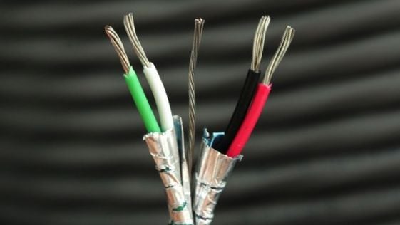
- For Modbus RTU, connect the Master and Slave devices using a serial communication interface (RS-485). Remember to follow the guidelines of the manual regarding the wires.
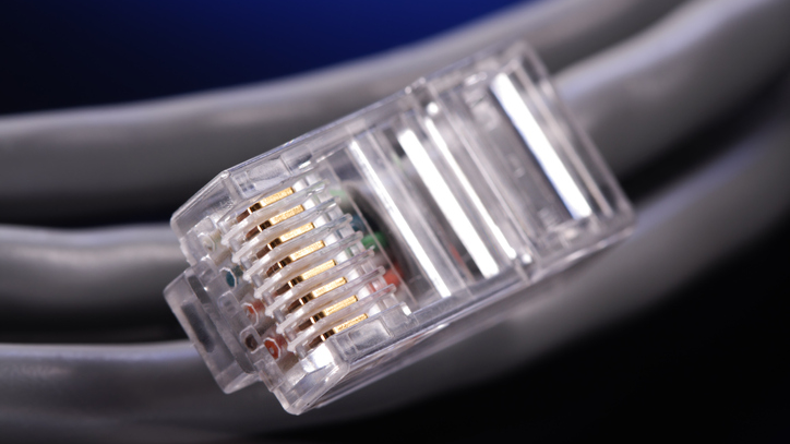
- For Modbus TCP/IP, establish an Ethernet connection between the Master and Slave devices, either directly or through a switch/router.
- Test the connection by sending queries to the Slave device and verifying the expected response.
- Once the connection is established, you can begin exchanging data between the Master and Slave devices using function codes and addresses.
Troubleshooting Common Modbus Issues
Like any communication protocol, Modbus may encounter issues that can hinder its performance and functionality. This is typically either hardware issues or protocol issues.
Communication Errors
One of the most common issues encountered when working with Modbus is communication errors. These can occur due to various reasons, such as incorrect addresses, faulty hardware components, or improper wiring.
To troubleshoot these issues, look into the manual of the Modbus device. You should ensure that all devices are configured correctly and have unique addresses within the network. Additionally, checking for loose connections and damaged cables can help resolve communication errors.
Device Addressing Issues
As mentioned earlier, accurate addressing is crucial for data exchange. If a device's logical or physical address is incorrect or overlaps with another device (typical if you have several of the same device), it can cause communication errors and prevent data transmission.
To troubleshoot this issue, you should verify the addresses of all devices and ensure that they are unique within the network.
Data Endian Issues
Modbus stores data in a 16-bit format, which may pose compatibility issues for devices that use different endians. If the Master and Slave devices have different endians, it can result in incorrect data interpretation and communication errors.
To resolve this issue, you will need to convert the data format on either the Master or Slave device to match the other's endian.
Data Integrity Problems
In some cases, data integrity issues can occur during data transmission, resulting in incorrect or missing data values. This could be due to electrical interference, poor signal strength, or misconfigured settings.
Troubleshooting steps for this issue include checking the wiring and signal quality and adjusting communication settings if necessary.
Bad Modbus Implementation
Another potential issue could be a faulty or incomplete Modbus implementation on the device. This could result in communication errors or incorrect data exchange. It is rare but I have experienced it. To troubleshoot this issue, ensure that you are using the correct function codes and addresses to communicate with the device. But if the Modbus documentation is lacking this could be the problem.
Short History of Modbus Protocol
The Modbus protocol was developed in 1979 by MODICON, a now-defunct company that specialized in industrial automation. It was created as a means of communication between programmable logic controllers (PLCs) and other electronic devices used in manufacturing.
The Modbus organization, formed in 1999, now maintains the protocol and its variants. Over the years, several improvements have been made to Modbus, including support for TCP/IP communication and enhanced security features.
Since its inception, the Modbus protocol has undergone several revisions and improvements to cater to the evolving needs of the industrial sector. It has become a widely adopted standard for industrial communication and is still in use today, with over 7 million Modbus devices installed worldwide.
Conclusion
The Modbus Protocol has become an essential tool in modern industrial automation, control systems, and data acquisition. Its simplicity and compatibility with various communication media make it a popular choice for connecting devices such as PLCs, sensors, actuators, motor drives, and other electronic components. With its widespread use in industries such as manufacturing, energy management, building automation, and transportation, Modbus has cemented its position as one of the most reliable and efficient communication protocols.